AIDE: Week Ten
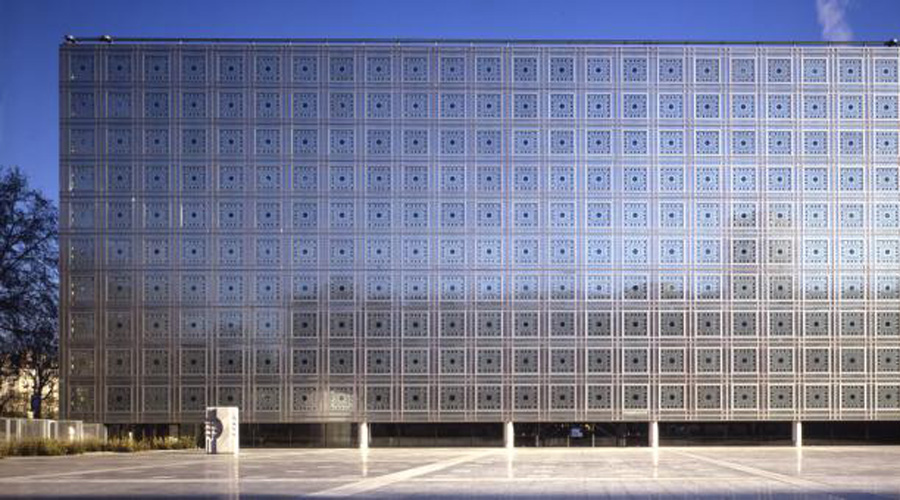
Jean Nouvel - Nemausus | 04/23
Architecture Documentary
Maison de Verre
Architecture 19 of 23 Pierre Chareu Maison de Verre
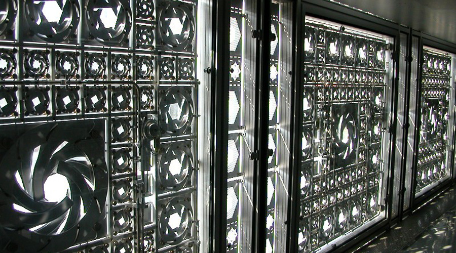
“For architects it represents the road not taken: a lyrical machine whose theatricality is the antithesis of the dry functionalist aesthetic that reigned through much of the 20th century.” – Nicolai Ousaroff (The New York Times, “The Best House in Paris,” 8/29/07) "Almost paradoxically, the house was both a “machine for living,” and an embrace of the arts and crafts movement, and the tour clearly demonstrates how artisanship and mechanization could coexist seamlessly in the Maison de Verre. The architect Pierre Chareau embodies this complexity, with his background as a furniture designer and his involvement in the C.I.A.M movement. It was even said that Le Corbusier often peeked into the courtyard during construction, as he worked and lived just nearby."
Compression, tension and stress
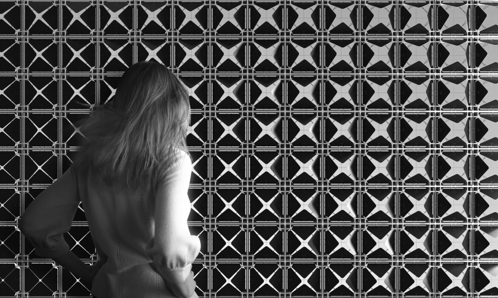
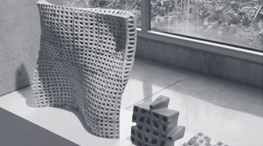
Softkill Algorithm
SoftKill algorithm combines the empirical and real-time character of a particle-spring setup with the computational model of finite element analysis found in typical Topological Optimization methods. Particles in a volume are redistributed(either added or removed) through calculating spring force.
Matter is then redistributed along principal lines of stress while structural agency is embedded through a procedural based logic of connections. What emerges is a thick layer of a porous, fibrous construct. Dissolving geometry through an abstract material articulation, resulting in a non-geometrical structure that is materially efficient, with a high degree of transparency and stiffness, while being extremely articulated, tactile, and ornate.
Softkill Design is a London based design collective (Nicholette Chan, Gilles Retsin, Aaron Silver, Sophia Tang) researching new methods of generative design for additive manufacturing. The unique workflow aims to produce intelligent designs which intuitively utilize 3D-print technology. Research was founded at the Architectural Association School of Architecture's Design Research Lab in the studio of Robert Stuart-Smith. Research prototypes were generously supported by Materialise, with additional support from VoxelJet, and Sirris.
Softkill Algorithm from Sophia Tang on Vimeo.
FEA
Finite Element Analysis is commonly used in aerospace, automotive and architectural engineering with 2d or 3d computer simulation models to solve complex shapes.
Initial work towards creating the analysis was done, separately, by Alexander Hrennikoff and Richard Courant during 1941-1942. Although the two used different approaches, they shared one essential idea: mesh discretization of a continuous domain into a set of discrete sub-domains, referred to as elements.
Starting in 1947, at Imperial College, Olgierd Zienkiewicz used these approaches to form what would later be called the Finite Element Method (FEM), building the pioneering mathematical formalism of the method. Today the Finite Element Method is used in any and all aspects of mathematics and physics; from visualization of how a car deforms in an asymmetrical crash to solving complex elasticity and structural analysis problems in civil and aeronautical engineering.
Key Benefits of Using FEA in Virtual Product Development
Reduce product development time and cost by reducing design iterations
Reduce product development time and cost by reducing the number of prototypes constructed
Reduce the amount of physical product testing, it is still very important to conduct some physical tests
Reduce time to market
Increase product quality through better understanding of how the product stands up to it's intended use
The earlier FEA is introduced into the product life cycle the better
Use FEA to drive product design
The Principal has over twenty years of varied FEA experience doing stress, thermal, and dynamic analyses
Solidworks FEA
FEA Tutorial Bending of a Cantilever Beam in SolidWorks.
SolidWorks takes a look at this classic cantilever beam fixed at one end with a sheer load or moment applied to the other end. Using one interface, you can review both the model and the deflection results to the analytical solution.
Join Esfand Kouhi from Intercad (http://www.intercad.com.au) as he explores SolidWorks FEA Simulation. This webcast will cover Simulation Seats in SolidWorks, Finite Element Definition, SolidWorks Simulation Interface, SolidWorks Simulation Options, SolidWorks Simulation pre-processing and SolidWorks Simulation post-processing.
The Rise of the Creative Class
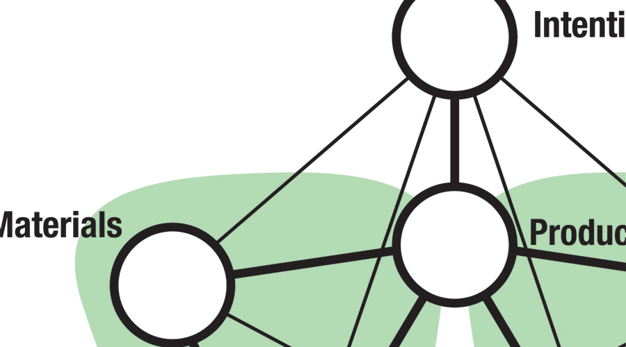
A relatively new class of workers who are young and passionate about their work, lifestyle and future. Money is not the motivation for endeavour - curiosity, challenge and respect are the key drivers.
This class of professional may have an impact upon your LCA mapping.
Download Presentation pdf
Assignment 3: Product Design
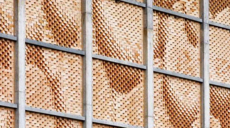
Propose a new building brick to replace a Boral hollow concrete brick to function in a complimentary manner, by way of design and material specification.
Hollow concrete brick assignment by studiobutcher on Sketchfab
Engineered Building Block - Range Extension
Engineer a complimentary and sympathetic alternative engineered block design to function alongside the range of Boral Series 150 concrete hollow building blocks.
Within the dimensional parameters of 390mm x 190mm x 140mm consider
Materials and components suited to Australian conditions.
Assemblies and processes targeting future building technologies.
Production materials and processes suited to medium volumes with an eye to development for higher volumes.
Fire risk building sites
Proposal requirements
At least two distinct materials and manufacturing processes in your design.
Structural chassis.
Components for passive and/or active lighting, air flow and retrofit.
Assessment criteria
30% of overall grade
Creativity of your design in regards to use of materials, processes and originality.
Technical understanding and application in regards to how the different components are designed and the level of detail shown.
Overall quality of the documentation of the design.
Note: there is no price point restriction on your design. It can be either a low end or a high end application or both.
Deliverables
Submission is a landscape PDF document (or website page) that includes the following:
A ¾ view of the product – hero shot
An exploded view of the product with part numbers
A cross section of the product identifying how the internal components are positioned and secured by your housings.
A bill of materials (BoM) corresponding to the exploded view that includes material type, manufacturing processes and surface treatment if applicable.
One page written overview of the design
Post your document to the Wiki (located in Week 14 folder on Blackboard) at 9am, Friday,
October 31stNovember 7th (revised to avoid a clash with design studio submissions.)
Shaping Profiles
Read the shaping profiles section of textbook.
Begin concept development of your brick proposal.
Consider:
Product orientation.
Materials.
How you are going to assemble the product.
Reclaimed, extruded, stamped, rolled or grown?
Presentation
Download this week's presentation here.
Topics covering:
Shaping Profiles.
Moulding
Casting
Bulk forming
Sheet forming
Rapid prototyping
Other various profiles